INDUSTRY INSIGHTS
In-Circuit vs Functional Testing in PCB Assembly
Engineers rarely see a finished circuit board before it passes through several layers of testing. A board may look complete after assembly, yet hidden issues can still exist in solder joints, components, or logic behavior. Manufacturing teams, therefore, rely on multiple testing methods. One practical question often comes up: how do in-circuit test and functional test approaches fit into the broader PCB assembly process?
Why PCB Testing Matters in Electronics Manufacturing
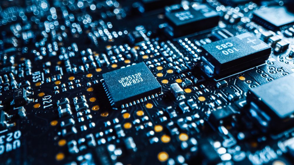
After a board moves through PCB assembly, it may appear complete. Components are placed, solder joints connect the circuitry, and the board resembles the final product. Yet visual inspection alone cannot reveal every issue inside a circuit.
Problems such as incorrect components, solder bridges, or electrical faults may remain undetected until the board is powered on. Testing helps identify these issues earlier in the manufacturing process.
For engineers working on prototypes or preparing production runs, structured testing cuts down on time spent diagnosing failures later. Methods such as in-circuit and functional testing examine the board from different perspectives, confirming that both individual components and the overall circuit behave as intended.
What Is PCB In-Circuit Test (ICT)?
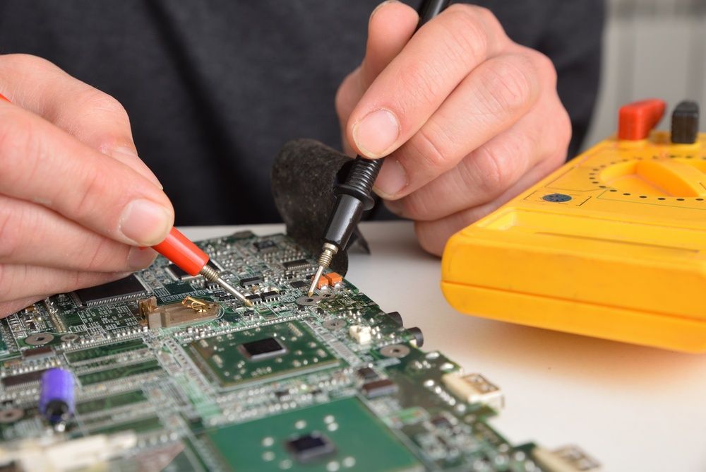
PCB in-circuit test examines individual components and electrical connections on an assembled board. The method typically uses a fixture called a bed-of-nails, where spring-loaded probes contact test points across the PCB. These probes measure resistance, capacitance, continuity, and other electrical values to verify that components are installed and connected correctly.
ICT usually occurs after placement processes such as
surface mount technology (SMT) in PCB assembly, once parts are soldered onto the board. At this stage, the system can scan many connection points quickly and spot issues like shorts, open circuits, or incorrect component values.
Because the test focuses on component-level verification, it catches manufacturing faults before the board moves into system-level testing.
What Is PCB Functional Testing (FCT)?
A PCB functional test evaluates how the assembled circuit behaves when powered and operating in real conditions. Instead of focusing on individual components, this test checks the board as a working system. Engineers apply power to the PCB and run test procedures that simulate actual use.
During the process, test equipment measures signals, outputs, and responses across the circuit. This can include checking communication interfaces, logic behavior, voltage levels, and timing performance.
Because functional testing evaluates the full circuit in operation, it reveals problems that component-level checks might miss. Logic errors, firmware faults, and unexpected signal behavior often appear only when the board runs as a complete electronic system.
In-Circuit Test vs Functional Test: Key Differences
Both testing methods examine different aspects of a circuit board during manufacturing and validation. In-circuit testing focuses on individual components and electrical connections, while functional testing looks at how the full circuit operates under real conditions. The comparison below shows how each method fits into manufacturing, troubleshooting, and final product verification.
| Feature | In-Circuit Test (ICT) | Functional Test (FCT) |
|---|---|---|
| What It Tests | Individual components and connections | Overall circuit functionality |
| Testing Level | Component-level | System-level |
| Typical Method | Bed-of-nails fixture probes | Power-on operational testing |
| Detects | Shorts, opens, wrong components | Logic errors and performance issues |
| Speed | Very fast in production | Usually slower and more complex |
| Best Used For | High-volume manufacturing | Final product verfication |
When to Use In-Circuit Testing in PCB Assembly
In-circuit testing works best when manufacturing teams need fast verification of individual components and connections across large batches of boards. Because the system checks electrical values directly at test points, it quickly identifies problems such as shorts, open circuits, or incorrect component placements.
This method is common in high-volume
printed circuit board (PCB) assembly, where speed and repeatability matter. A bed-of-nails fixture can access many points across the board within seconds, helping production teams catch manufacturing defects early.
ICT works particularly well for designs with accessible test points and stable component layouts, so it becomes a reliable step during production runs.
When Functional Testing Is the Better Choice
Functional testing becomes useful when engineers need to observe how the circuit behaves during operation. Instead of measuring individual components, the process powers the board and runs test procedures that simulate real use conditions.
This method helps identify problems that component-level checks may miss. Software behavior, communication interfaces, signal timing, and power performance often appear only when the circuit runs as a complete system.
Functional testing is commonly used during prototype validation, product development, and final verification before a design enters production. By evaluating the board in realistic operating conditions, engineering teams gain greater confidence that the design performs reliably as intended once integrated into the final product.
How ICT and Functional Testing Work Together
In many manufacturing workflows, both testing methods appear at different stages of the process. In-circuit testing typically comes first, catching component placement errors, shorts, and open connections shortly after assembly. This step helps manufacturing teams spot hardware faults before more complex system testing begins.
Functional testing usually follows as a later validation step. Once the board powers on, engineers run operational tests that confirm the circuit behaves correctly in realistic conditions.
This combined approach is especially useful during
PCB prototyping, when teams refine early hardware versions. Component-level checks isolate manufacturing defects, while system-level testing reveals performance issues that show up only during real operation. Together, these methods create a smoother path from early prototypes to stable production designs.
Need Reliable PCB Assembly Testing? Call Ninja

Testing plays a quiet but important role in moving a design from concept to dependable hardware. When circuits pass through structured validation, engineering teams gain confidence that boards leaving the manufacturing floor will perform as expected in real applications.
Ninja Circuits works with hardware teams building prototypes and short production runs where reliable testing matters. Their focus on quick-turn builds helps engineers evaluate designs, troubleshoot issues, and keep development moving without long manufacturing delays.
When a project is ready for assembly and validation, the next step is straightforward.
Contact Ninja Circuits today to request a quote and start your next PCB build with confidence and speed.
INDUSTRY INSIGHTS