INDUSTRY INSIGHTS
Through-Hole vs. Surface-Mount: PCB Assemblies Compared
SHARE POST
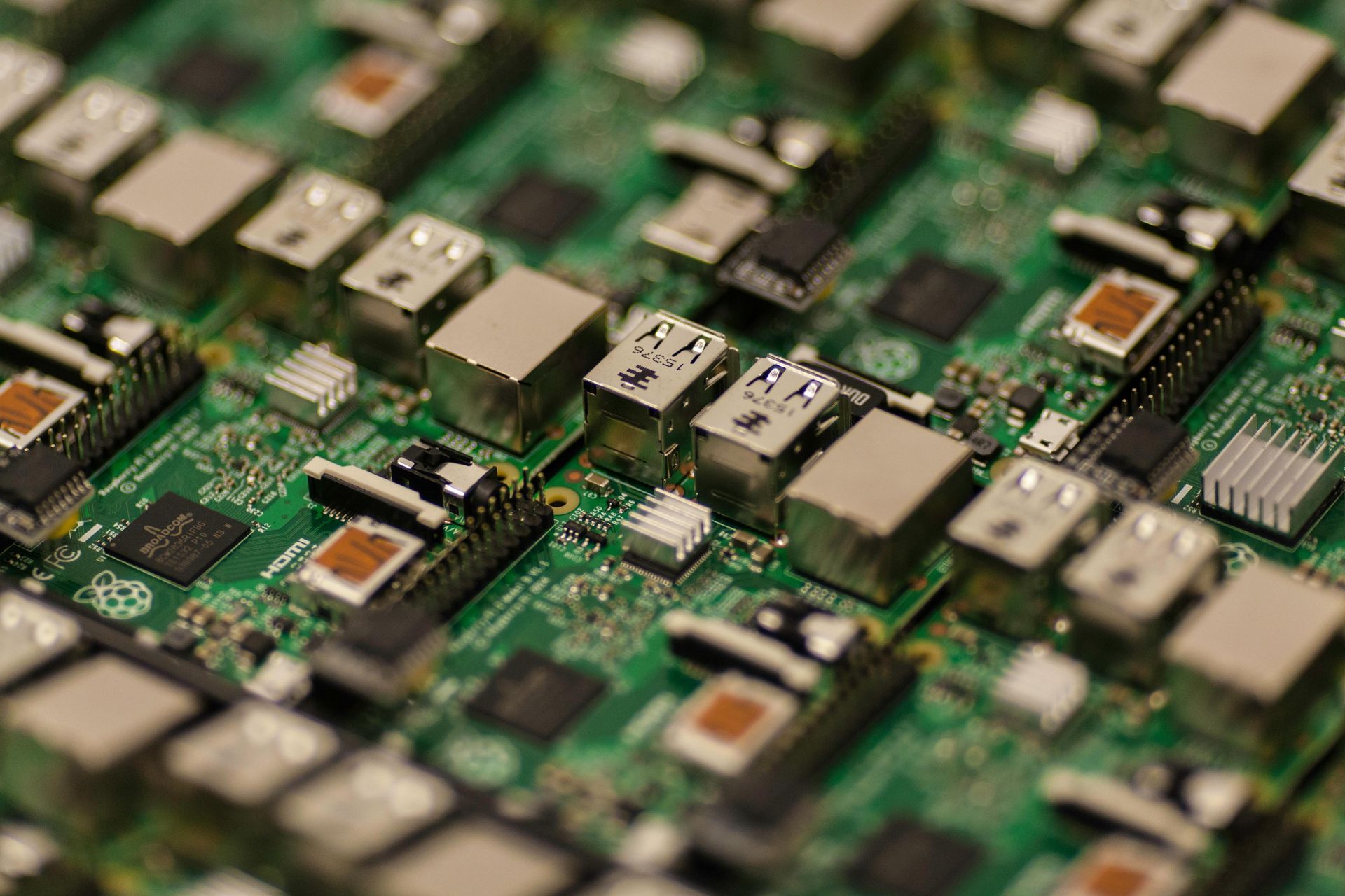
Choosing between surface-mount and through-hole assembly comes down to the board’s component density, electrical performance, mechanical loads, production volume, and plans for rework. In many designs, the strongest answer is a mix of both: SMT for compact, automated assembly and through-hole for parts that face greater physical stress or benefit from easier hands-on rework.
At Ninja Circuits’ U.S.-based assembly shop, both methods are part of quick-turn prototype and short-run PCB work, including mixed-technology builds. The practical question is where each assembly method fits the design, manufacturing process, and testing plan.
How Through-Hole Assembly Works
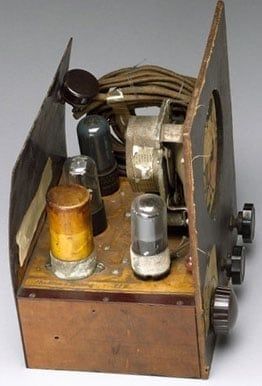
Through-hole assembly starts with component leads inserted into drilled PCB holes, then soldered on the opposite side. Once largely done by hand, the process can now use wave or selective soldering for faster, more consistent assembly. Through-hole PCB assembly is especially useful when mechanical strength matters because the leads pass through the board and create a strong physical connection. It also works well for hand assembly and rework, needs no solder-paste stencil, and is more forgiving when a board has some warp or twist. The tradeoff is space and processing: drilled holes consume routing area, components are generally larger, and added assembly steps can increase time and cost as production volume grows.
How Surface Mount Assembly Works
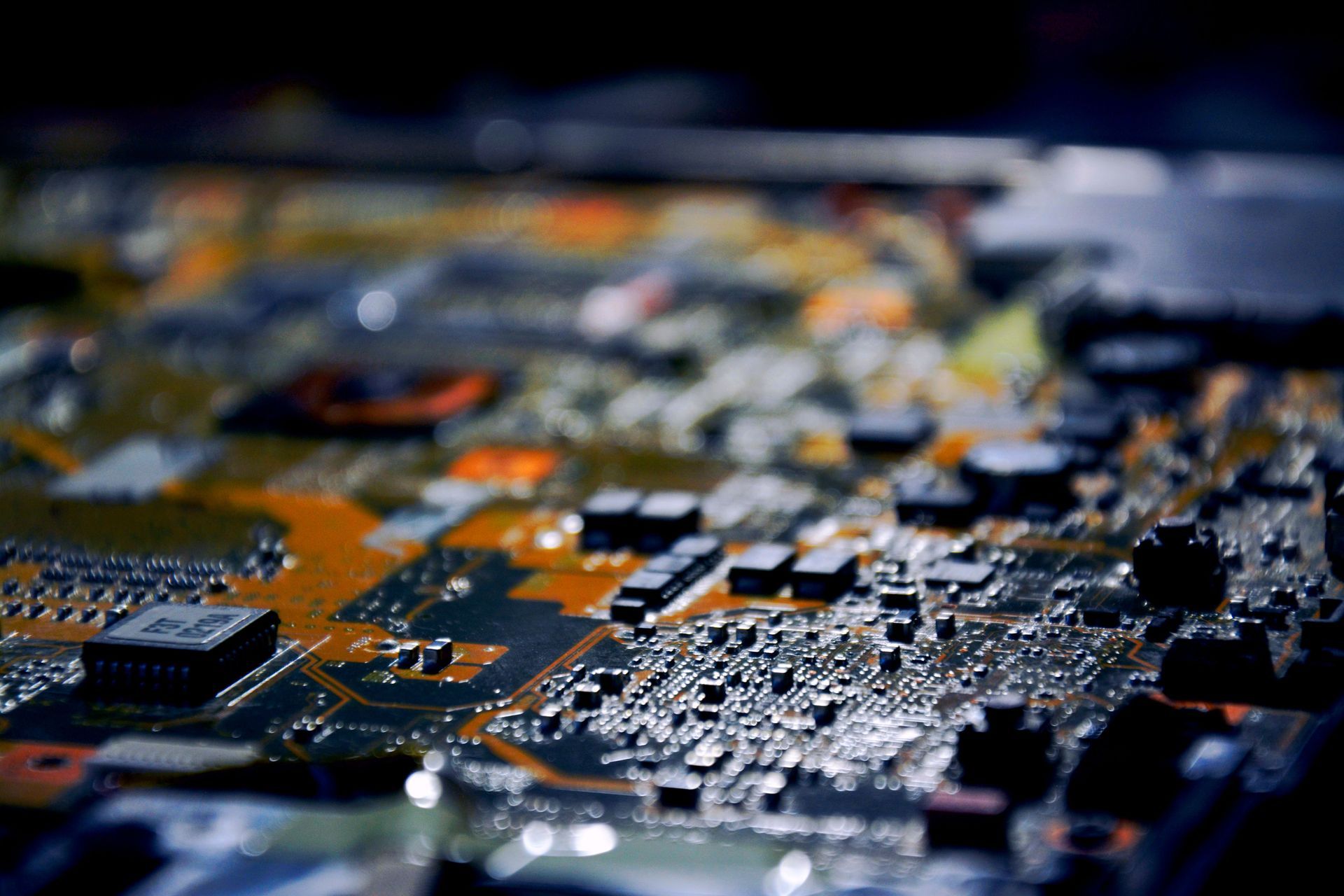
Surface mount assembly places components directly onto pads on the PCB instead of passing leads through drilled holes. Solder paste is applied through a stencil, automated pick-and-place equipment positions the components, and reflow soldering forms the connections. Components can also populate both sides of the board when space is tight. SMT and BGA assembly fit designs that need high component density, a smaller footprint, or fast automated production. Shorter connections can also benefit signal integrity in high-speed circuits. Once production volume rises, automation can reduce assembly cost significantly. The tradeoffs include more specialized equipment, tighter process control, and more challenging hands-on rework for fine-pitch packages.
Surface Mount vs Through Hole on Key Design Factors
The right assembly method depends on what the board needs to handle in use and during production.
| Design Factor | Surface Mount | Through Hole |
|---|---|---|
| Density and size | Higher density, smaller boards | Larger components and drilled holes |
| Signal integrity | Shorter connections suit high-speed circuits | Longer leads add parasitics |
| Mechanical reliability | Strong for typical use | Better for vibration and physical stress |
| Thermal and power | Works well with compact thermal designs | Often chosen for large, high-power parts where PCB thermal management shapes the layout |
| Cost | Automation lowers cost at volume | Added processing can raise volume costs |
| Rework | Fine-pitch parts can be challenging | Easier to access and hand-rework |
When Through Hole Is the Right Call
Through-hole earns its place when physical stress, power, repair access, or component availability outweigh board-density concerns. It is especially practical for:
- High-vibration applications: Military, aerospace, and automotive underhood electronics benefit from leads anchored through the PCB.
- High-power components: Transformers, large capacitors, and mechanically stressed connectors often fit through-hole construction well.
- Field-repairable equipment: Accessible leads simplify troubleshooting and component replacement.
- Legacy designs: Older or specialized components may only come in through-hole packages.
- Early prototypes: Hand assembly makes through-hole useful for low-quantity builds where engineers expect component swaps during validation.
For these designs, the extra board space can be a reasonable trade for physical strength and accessible rework.
When Surface Mount Is the Right Call
Surface mount becomes the practical choice when board space, signal performance, package selection, or production speed drives the design. It fits especially well for:
- Dense multilayer boards: Small components preserve valuable PCB real estate for routing and added functionality.
- High-speed and RF circuits: Shorter connections help control parasitics and protect signal integrity.
- Miniaturized electronics: Consumer electronics and medical devices often depend on compact SMT packages.
- Higher production volumes: Automated placement and reflow keep assembly fast while reducing per-board labor costs.
- Advanced packages: BGAs, QFNs, and many fine-pitch components are designed specifically for surface mounting.
These advantages become increasingly important as boards get smaller, faster, and more densely populated.
Mixed assembly is common in industrial, automotive, and communications electronics because different components face different design pressures. High-density ICs such as MCUs, sensors, and RF devices can use SMT to conserve space, while connectors, relays, and larger power components use through-hole connections where added mechanical strength matters.
Assembly sequence also affects the design. SMT components are typically placed and reflowed first. Through-hole parts are inserted afterward and soldered using wave or selective soldering, depending on the board layout and component mix. Ninja Circuits handles both assembly methods, including mixed-technology builds, so prototypes with compact circuitry and mechanically stressed components can move through one coordinated assembly process.
Assemblies that combine large through-hole components with smaller surface-mount devices can create challenges during reflow, especially when the components require very different thermal profiles. Ninja Circuits uses
vapor phase reflow, which provides uniform heat transfer across the entire assembly and makes it easier to develop a reliable soldering profile for complex, mixed-component builds.
When to Combine Both on One Board
For PCB prototyping, assembly speed depends on more than choosing SMT or through-hole. Component availability, board complexity, inspection needs, and mixed-assembly steps can all affect the schedule. A clean build package with accurate Gerber files, BOM data, and placement files reduces preventable back-and-forth before assembly begins.
Parts availability deserves the same attention. A long-lead component can erase days saved on a quick-turn build, while fine-pitch packages or mixed assemblies may add inspection and soldering steps. Planning for likely component swaps also keeps early rework practical. When those details are settled before release, engineers can spend less time resolving manufacturing questions and more time testing the prototype, finding design issues, and preparing the next revision.
Trust Ninja Circuits with Your PCB Assembly Project
The through-hole vs. surface-mount decision should reflect how the finished board will function, how much space is available, and what the components will experience in service. Many designs benefit from using both methods, pairing compact SMT circuitry with through-hole connections where mechanical strength or accessible rework matters.
Ninja Circuits specializes in quick-turn prototypes and short-run production from its U.S.-based facility. Capabilities across SMT, BGA, through-hole, selective soldering, vapor-phase reflow, 3D AOI, and X-ray inspection keep complex assemblies moving through a coordinated process. When the design is ready to leave the screen and reach the test bench.
INDUSTRY INSIGHTS